Modern exhaust aftertreatment faces a massive engineering dilemma. Neutralizing toxic gases requires a massive surface area to facilitate chemical reactions. However, modern exhaust systems also demand incredibly low backpressure and absolute extreme thermal tolerance. If you restrict exhaust flow too much, you severely damage engine performance.
Standard structural materials simply melt, warp, or choke the exhaust flow under these brutal operating conditions. We solve this problem by relying on the Honeycomb Ceramic Catalyst as the accepted industry-standard solution. It provides a highly precise balance of thermodynamic stability, optimal fluid dynamics, and exceptional cost-efficiency compared to pure metallic alternatives.
Engineering and procurement teams must evaluate these substrates carefully. They face immense pressure to meet stringent global emission mandates, including Euro 6 and strict EPA standards. In this guide, we explore how you can evaluate, source, and implement these substrates properly. You will learn the exact evaluation criteria needed to hit emission targets while maintaining peak engine performance.
Key Takeaways
Geometric Efficiency: The honeycomb structure maximizes surface area for precious metal washcoats while minimizing exhaust backpressure.
Thermal Shock Resistance: Manufactured primarily from cordierite, these substrates endure rapid temperature fluctuations without fracturing.
Cost-to-Performance Ratio: Ceramic carriers offer a more cost-effective baseline than metallic substrates for the vast majority of OEM and aftermarket applications.
Application Versatility: Functions as the foundational architecture for Three-Way Catalysts (TWC), Diesel Oxidation Catalysts (DOC), and particulate filters.
The Core Engineering Problem: Heat, Flow, and Chemical Conversion
Engineers face conflicting requirements when designing an exhaust aftertreatment system. You cannot simply place a block of reactive metal into an exhaust pipe. The system must process massive volumes of highly pressurized, superheated gas in fractions of a second. To measure success, we must look at a few non-negotiable performance criteria.
Rapid Light-Off Time: The catalyst must reach its active operating temperature (usually around 300°C) almost instantly after a cold engine start.
Sustained High-Temperature Operation: The system must survive continuous exposure to exhaust gases exceeding 800°C under heavy engine loads.
Low Physical Degradation: The component must resist severe vibrations, impacts, and thermal shocks for over 150,000 miles of real-world driving.
The primary constraint in this design is fluid dynamics. High conversion efficiency requires you to slow down the exhaust gas. It needs time to make physical contact with active precious metals like platinum (Pt), palladium (Pd), and rhodium (Rh). But if you create excessive restriction, you choke the engine. High backpressure ruins fuel economy, reduces horsepower, and can damage internal engine components. We must maximize surface area while minimizing physical obstruction.
This explains why ordinary structural metals fail so quickly in catalytic applications. Standard steel or aluminum alloys oxidize rapidly, melt, or warp when exposed to raw exhaust gas. They expand aggressively when heated. This expansion causes any applied chemical coatings to crack and flake off. A specialized carrier is strictly necessary to host the chemical reactions without destroying itself in the process.
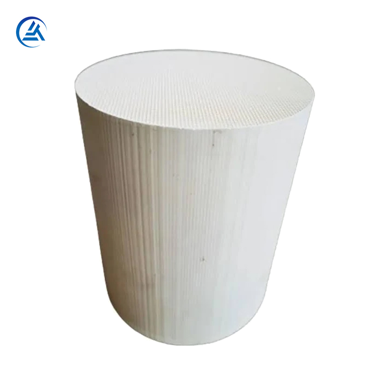
How the Ceramic Honeycomb Catalyst Architecture Works
To overcome the limitations of standard metals, the industry turned to advanced material science. We rely heavily on magnesium alumina silicate, commonly known as cordierite. Cordierite is the universally preferred automotive ceramic substrate for several highly specific reasons. Most notably, it features an extremely low coefficient of thermal expansion.
When you expose cordierite to rapid, extreme heating, its dimensions barely change. It does not swell or warp like metal. This dimensional stability is critical because it prevents the internal matrix from shattering when a cold car suddenly accelerates, dumping scorching gas into a freezing exhaust pipe.
The internal geometry of this substrate is just as important as the material itself. The honeycomb design features thousands of tiny parallel channels. This specific channel geometry dictates the fluid dynamics of the system.
It forces turbulent exhaust gas into a smooth, laminar flow.
It massively reduces turbulence.
It significantly lowers backpressure compared to historical pellet-based or random-matrix designs.
By forcing the gas through these straight, uniform pathways, we expose every molecule to the channel walls without creating chaotic, flow-choking vortexes.
We must also look at the washcoat interface. The bare ceramic itself does not clean the exhaust; it merely acts as the host. The porous microscopic structure of a ceramic catalyst carrier allows the active washcoat to adhere securely. Manufacturers apply a slurry of alumina and precious metals to the honeycomb. The micro-pores in the cordierite absorb this washcoat like a sponge. Once baked, this mechanical bond locks the active metals in place. It prevents catalyst blow-out, ensuring the system remains effective over a complete lifecycle of 150,000 miles or more.
Ceramic vs. Metallic Substrates: A Decision Framework
While ceramic dominates the market, metallic foil substrates also exist. Procurement and engineering teams must constantly evaluate these two options. We base this decision framework on thermal mass, physical durability, and overall scalability.
Thermal mass dictates how quickly the catalyst achieves "light-off." Metallic foils generally have lower thermal mass than older, thick-walled ceramics. They heat up faster, which helps reduce cold-start emissions. However, modern manufacturing techniques allow us to produce ultra-thin ceramic walls. These advanced thin-wall ceramics drastically lower the thermal mass, effectively closing the light-off gap between ceramic and metallic options.
Durability and canning present another major difference. Ceramic is inherently fragile before installation. It cannot be welded or bolted directly to a steel exhaust pipe. Ceramic requires specialized intumescent mats for "canning." We wrap the ceramic core in this expanding mat and press it into a steel shell. The mat acts as a shock absorber, protecting the brittle ceramic from chassis vibrations and physical impacts. In contrast, metallic substrates are brazed directly to the outer steel shell. They handle physical shock better but suffer from severe thermal expansion issues.
We must also address the economic reality of manufacturing. Cost and scalability heavily favor ceramic. The materials are cheaper to source, and the extrusion manufacturing process scales incredibly well for high-volume production. This economic advantage explains why the ceramic honeycomb catalyst remains the dominant choice for standard OEM vehicle production. We typically reserve metallic substrates for high-performance sports cars or space-constrained specialty vehicles where extreme flow rates justify the premium cost.
Comparison Chart: Substrate Material Attributes
Substrate Material Comparison Table
| Attribute | Ceramic (Cordierite) | Metallic Foil |
| Thermal Expansion | Extremely Low | High |
| Manufacturing Cost | Highly Cost-Effective | Premium / Expensive |
| Assembly Method (Canning) | Requires Intumescent Mat | Directly Brazed to Shell |
| Best Application Fit | High-volume OEM, standard vehicles | High-performance, tight spaces |
Key Evaluation Criteria for Sourcing and Implementation
When selecting a substrate for a specific vehicle platform, engineers use exact mathematical criteria. You cannot buy a generic substrate and expect it to pass regulatory testing. We focus primarily on cell density, wall thickness, and specific application matching.
We measure cell density in Cells Per Square Inch (CPSI). Standard passenger vehicles typically utilize substrates ranging from 400 to 600 CPSI. You must manage a strict trade-off here. A higher CPSI (like 600 or 900) provides vastly more surface area. This yields better chemical conversion rates. However, more cells mean narrower channels, which increases backpressure. A lower CPSI (like 200 or 300) drops the backpressure but reduces the active surface area, risking failed emission tests.
Wall thickness plays a closely related role. Over the last decade, manufacturers pushed for ultra-thin walls. We routinely see wall thicknesses of 2 to 4 mils (thousandths of an inch). Thinner walls increase the open frontal area of the substrate. They reduce backpressure and lower the thermal mass, promoting faster light-off. The engineering trade-off is mechanical strength. Ultra-thin walls are fragile. They require precise canning procedures to prevent cracking during installation.
Application matching dictates the final structural design. A gasoline engine environment differs vastly from a diesel environment. For a gasoline engine, we use a standard Three-Way Catalyst (TWC) configuration. The exhaust gas flows smoothly through the open channels.
Diesel applications introduce heavy soot loading. A Diesel Oxidation Catalyst (DOC) uses a traditional flow-through honeycomb structure. But a Diesel Particulate Filter (DPF) requires a modified approach. We use a wall-flow structure for DPFs. We plug alternating channels in the honeycomb. This forces the exhaust gas to push through the porous ceramic walls. The walls physically trap the soot while letting the gas escape. These diesel environments undergo active regeneration cycles, pushing temperatures to extremes to burn off the trapped soot. The substrate must handle these brutal structural stresses without cracking.
Implementation Risks and Substrate Failure Modes
Even a perfectly specified substrate can fail if the surrounding engine system malfunctions. We categorize substrate failures into three main groups: thermal degradation, chemical poisoning, and mechanical shearing. Understanding these risks helps you prevent costly warranty claims.
Thermal Degradation (Melting): A well-tuned engine keeps exhaust temperatures within a safe operating window. However, if an engine experiences misfires, unburned fuel dumps directly into the exhaust pipe. This raw fuel hits the active catalyst and ignites inside the carrier. These internal fires easily exceed the ceramic’s melting point (typically above 1,200°C). The internal honeycomb walls liquefy and fuse together. We call this a core collapse. The exhaust becomes completely blocked, and the engine stalls.
Chemical Poisoning: The ceramic substrate itself is chemically inert. However, the precious metal washcoat is highly vulnerable to contaminants. If a vehicle burns excessive engine oil, phosphorus additives in the oil travel down the exhaust. They bake onto the catalyst, forming a hard, glassy glaze over the washcoat. Sulfur from low-quality fuel does the same thing. This glaze acts as a barrier. It renders the underlying honeycomb architecture totally useless because the exhaust gas can no longer touch the active metals.
Mechanical Shearing: The ceramic core is brittle. If the manufacturing facility uses improper canning techniques—such as incorrect mat pressure—the substrate can slip inside its steel shell. Severe chassis impacts or severe off-roading can also cause damage. The ceramic impacts the steel casing and fractures. You will often hear this failure before you see it; it causes a distinct, loud exhaust rattling sound. Once fractured, the exhaust gas bypasses the broken channels, causing instant emission test failures.
Shortlisting Logic & Next Steps for Procurement
Procurement teams need a structured approach to validate suppliers. Not all ceramic substrates offer the same quality, even if the CPSI specs look identical on paper. You need to validate supplier quality by looking beyond basic dimensions.
Evaluate the substrate for homogenous porosity. The pores must be evenly distributed so the washcoat absorbs perfectly.
Demand minimal dimensional variance. If the exterior diameter varies by even a fraction of a millimeter, the canning mat will not compress evenly, leading to mechanical shearing later.
Require proven thermal shock testing documentation. The supplier must prove the substrate can survive thousands of extreme hot-to-cold cycles.
Regulatory compliance is your ultimate target. You must ensure the chosen substrate matrix can support the specific washcoat volume required to pass localized lifecycle emission regulations. A cheaper substrate might have a lower porosity, meaning it cannot hold enough platinum to pass Euro 6 testing after 100,000 miles of wear.
Your actionable next step is moving from substrate selection to prototyping. Do not operate in a silo. You must integrate your substrate choice with a washcoat partner and a canning facility immediately. Provide them with your selected dimensional specs and cell density data. They will coat a prototype batch and run hot-shake durability tests to ensure the complete assembly works cohesively.
Conclusion
A properly engineered exhaust aftertreatment system requires more than just reactive chemicals. The substrate serving as the foundation must withstand unimaginable abuse while maintaining precise fluid dynamics. The honeycomb ceramic catalyst is not just a passive pipe; it is a highly engineered intersection of material science and aerodynamic flow.
We must optimize the geometric efficiency of these carriers to balance the delicate trade-off between chemical conversion rates and engine backpressure. Whether you are dealing with gasoline TWCs or heavy-duty diesel DPFs, the core cordierite structure remains the industry standard for scalability and thermal resilience.
Careful specification of CPSI, wall thickness, and base material quality is absolutely critical. You must align your substrate choice with your washcoat chemistry and canning processes. Following these exact technical evaluations ensures you achieve long-term regulatory compliance, maximize engine performance, and avoid catastrophic warranty claims in the field.
FAQ
Q: Why can't we use normal metals instead of a ceramic catalyst carrier?
A: Normal metals oxidize and degrade rapidly at 800°C+ exhaust temperatures. They also undergo severe thermal expansion, which causes the active precious metal washcoat to crack and flake off. Ceramic provides unmatched dimensional stability under these extreme thermal shocks.
Q: Does the honeycomb structure restrict exhaust flow and hurt performance?
A: While any physical barrier introduces some backpressure, the straight, parallel channels of a honeycomb matrix are mathematically optimized. They offer the lowest possible flow restriction while maintaining the massive surface area required for effective chemical reactions.
Q: Why is the replacement of a ceramic honeycomb catalyst so expensive?
A: The high cost is rarely the ceramic substrate itself. The massive expense comes from the platinum, palladium, and rhodium washcoat applied to the honeycomb structure. These rare precious metals are strictly required for the chemical reduction of NOx and oxidation of CO/HC.
Q: What is the difference between a ceramic substrate in a DOC vs. a DPF?
A: A Diesel Oxidation Catalyst (DOC) uses a flow-through honeycomb structure. A Diesel Particulate Filter (DPF) uses a wall-flow structure, where alternating channels are plugged, forcing exhaust gas through the porous ceramic walls to physically trap raw soot.


