A diesel particulate filter change is a high-stakes, capital-intensive repair. Mechanics and vehicle owners face immense pressure to execute this procedure flawlessly. Unfortunately, most premature failures of new replacement units occur because of flawed installation practices. Technicians often swap the physical hardware without addressing upstream engine faults. They also frequently forget to reset critical software parameters within the engine computer. This oversight directly causes rapid re-clogging and expensive repeat failures.
We designed this guide as an evidence-based, start-to-finish framework. Our goal is to help you execute a compliant, long-lasting replacement. You will learn how to navigate the entire process smoothly. We cover everything from initial diagnostic verification to post-install software adaptation. By following these strict protocols, you protect the new hardware and ensure reliable engine performance for years to come.
Key Takeaways
Hardware replacement resolves the symptom, not the root cause; upstream diagnostics are mandatory prior to installation.
A successful diesel particulate filter change requires ECU parameter resets to prevent the system from applying old ash-load calculations to a new filter.
Evaluating a DPF Finished Product requires balancing emissions compliance, backpressure tolerances, and vehicle-specific integration (e.g., BMW vs. Toyota architectures).
Reusing degraded differential pressure or exhaust gas temperature (EGT) sensors significantly increases the risk of immediate replacement failure.
Pre-Replacement Diagnostics: Utilizing a DPF Failure Guide
Before removing any exhaust hardware, you must define clear success criteria. You need to verify irreversible damage before committing to an expensive swap. Look for signs of core melting, structural failure, or maximum ash accumulation. Do not guess based on dashboard warning lights alone. Rely on a comprehensive DPF Failure Guide to confirm the existing unit is truly beyond chemical recovery or forced regeneration.
Next, you must rule out false positives. Mechanics routinely condemn the exhaust filter when upstream engine components are actually causing the restriction. You must assess these specific systems before proceeding:
EGR Valves: Sticking valves allow excessive soot into the exhaust stream.
Fuel Injectors: Leaking injectors dump raw fuel, which ignites and melts the substrate.
Turbocharger Seals: Blown seals leak engine oil directly into the exhaust housing.
A data-driven assessment is mandatory. Connect your bidirectional OBD2 scanner to the vehicle. Measure the differential pressure at idle and under heavy load. You must compare these live data numbers against official manufacturer baselines. For instance, healthy idle backpressure typically sits between 5 and 15 mbar. If your scanner shows over 100 mbar at idle, a severe physical restriction exists.
Consider the massive implementation risk involved here. Replacing the exhaust hardware without fixing an underlying over-fueling issue wastes time and money. The engine will continue producing abnormal amounts of soot. This heavy soot load will completely clog the new unit within a few hundred miles. You must resolve all upstream engine codes first.
Selecting the Right Unit: DPF Finished Product and Compliance
Choosing the correct replacement component directly dictates long-term emissions compliance and structural durability. You must evaluate different solution categories carefully. Start by comparing OEM versus aftermarket options. Think about longevity, warranty stipulations, and internal substrate materials.
High-quality units use Silicon Carbide (SiC) because it handles extreme temperatures exceptionally well. Cheaper aftermarket alternatives often use Cordierite. Cordierite melts at lower thermal thresholds and cracks easier under stress. You must weigh these material differences against your driving environment.
Substrate Material Comparison
| Material Type | Melting Point | Thermal Durability | Ideal Application |
| Silicon Carbide (SiC) | ~2700°F (1482°C) | Excellent | Heavy-duty, commercial, frequent city driving |
| Cordierite | ~2200°F (1204°C) | Moderate | Light-duty, consistent highway driving |
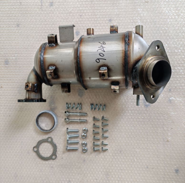
You should prioritize complete assemblies over cheaper alternatives. Sourcing a complete DPF Finished Product offers massive structural advantages over weld-in cores. Ready-to-bolt-on units guarantee factory-level structural integrity. They eliminate dangerous welding errors. They also prevent micro-leaks near sensor bungs.
Manufacturer-specific tolerances vary wildly across the industry. Backpressure thresholds differ heavily across vehicle platforms. A Toyota Replacement DPF requires vastly different flow rates compared to domestic trucks. Similarly, a BMW Replacement DPF integrates very specific sensor bung angles to fit inside cramped European engine bays. You must select units engineered for exact geometric fitment.
Finally, address legal compliance and risk mitigation. Some owners consider software bypasses or hardware deletes. We strongly advise against these practices. Deleting emissions equipment carries massive legal, financial, and operational risks. Strict emissions compliance protects commercial operations from severe penalties. It also preserves vehicle resale value. Do not bypass the system under any circumstances.
Hardware Installation SOP: Pitfalls and Sensor Validation
Executing a physical swap demands strict standard operating procedures. Preparation and teardown require patience. You must safely remove delicate heat shields first. Apply high-quality penetrating oil to unseize baked-on sensors. Let the oil soak to prevent stripping the threads. Inspect the exhaust mating surfaces carefully. Any warping or deep pitting will cause exhaust leaks later.
You face mandatory hardware replacements during this stage. You must replace all gaskets, crush rings, clamps, and V-bands. Reusing old, heat-cycled hardware creates tiny micro-leaks. These invisible leaks skew upstream sensor data. The engine control module needs perfectly sealed pressure readings to calculate soot loads accurately.
Sensor health verification is highly critical. You must establish strict criteria for testing components during the swap.
Test sensor resistance using a digital multimeter.
Check the entire wiring harness for heat damage or chafing.
Replace any sensors showing erratic live data during prior diagnostic scans.
Discard Differential Pressure Sensors if they have exceeded 100,000 miles.
Mechanics often destroy new filters by mishandling sensors. We must detail the severe risks of cross-threading or improper torque specifications. Apply specialized high-temperature anti-seize compound to all sensor threads. Torque them to exact factory specifications using a calibrated wrench. Over-tightening crushes the internal ceramic elements inside EGT probes.
Structural alignment prevents future mechanical damage. You must ensure proper exhaust hanging and tension relief. A misaligned exhaust system causes extreme stress fractures. As the new housing undergoes intense thermal cycling during regeneration, uneven tension will crack the steel welds. Hang the system loosely, align all flanges perfectly, and then tighten clamps incrementally.
The Software Mandate: ECU Reset and Parameter Adaptation
Many mechanics finish bolting up the physical hardware and immediately hand the keys back to the owner. This action represents a fatal error. The Engine Control Unit (ECU) operates on a mathematical ash model. It assumes the filter is still completely full of ash. It does not magically know you installed fresh hardware. You must explicitly reprogram the system to recognize the new unit.
Follow proper reset procedures using an advanced bidirectional scan tool. You cannot perform this step with a basic code reader.
Turn the ignition on without starting the engine.
Clear all historical Diagnostic Trouble Codes (DTCs) from the memory.
Navigate to the specific engine adaptations or service menu.
Locate and execute the "New DPF Learned" or "Ash Counter Reset" command.
Sensor calibration happens next. You must calibrate the differential pressure sensor to zero atmospheric pressure. Execute this function before you ever start the engine. The ECU desperately needs this zero-point baseline. It uses this baseline to measure future soot accumulation accurately.
Understand the severe consequences of omission here. Skipping this software adaptation practically guarantees immediate failure. The ECU will force hyper-frequent, aggressive active regenerations because it thinks the filter remains blocked. These unnecessary burn cycles will thermally shock the fresh substrate. The extreme heat will melt the new ceramic core within weeks.
Post-Replacement Validation and Test Drive Protocols
Do not release the vehicle back to the customer yet. You must conduct thorough initial startup checks. Start the engine and let it idle. Monitor for exhaust leaks at all mating flanges. Listen closely for hissing sounds. Check your scanner for plausible live data from the temperature sensors. EGT readings should rise steadily as the engine warms up.
Next, perform a structured validation drive. You must follow specific drive cycle requirements to trigger the vehicle's internal readiness monitors. Highway driving provides the best conditions.
Drive continuously for 20 to 30 minutes without stopping.
Maintain steady speeds between 45 and 60 mph.
Keep engine RPM steady around 2000 to 2500 RPM.
Ensure the engine coolant reaches normal operating temperature early in the drive.
Dynamic data logging confirms ultimate success. Monitor the differential pressure under heavy acceleration during your drive. The pressure must stay well below the maximum threshold limits specified by the manufacturer. Verify soot accumulation metrics align with expected baseline behavior. If pressure spikes drastically, stop driving immediately. You may have a crushed sensor pipe or a collapsed muffler downstream.
Final sign-off requires strict evaluation criteria. Check the ECU one last time. Ensure absolutely no pending codes exist. Confirm anomalous backpressure spikes are completely absent. Check the exhaust tailpipe for any signs of black soot. Only when all data parameters read perfectly can you safely release the vehicle.
Conclusion
A successful replacement is a deeply integrated procedure. It requires equal attention to physical hardware and digital software. You cannot achieve lasting success by merely swapping metal pipes. Upstream diagnostics, strict installation protocols, and precise software coding are all vital steps in this ecosystem.
We emphasize the critical importance of following OEM installation protocols. Resolving upstream engine maintenance ensures long-term operational health. You protect the massive initial investment by doing the job correctly the very first time. Cutting corners always leads to catastrophic substrate melting.
If you lack the proper equipment, consult certified emissions technicians immediately. Always source compliant replacement units from reputable manufacturers. Acquire the necessary bidirectional diagnostic tools before beginning the teardown. Following this comprehensive framework guarantees optimal engine performance and absolute emissions compliance.
FAQ
Q: Do I always need to reset the ECU after a diesel particulate filter change?
A: Yes. The ECU continuously calculates internal ash accumulation. If you skip the reset, the computer assumes the new unit is already clogged. It will trigger aggressive, constant regeneration cycles. This continuous extreme heat will rapidly melt and destroy the brand-new substrate.
Q: Can I reuse my old sensors on a new DPF?
A: We highly recommend replacing them. While reusing sensors saves minor upfront costs, degraded sensors send inaccurate data to the ECU. High-mileage differential pressure sensors frequently drift out of calibration. This inaccuracy prevents normal regeneration, causing your new filter to clog almost immediately.
Q: Why did my new DPF clog immediately after installation?
A: Immediate clogging stems from unresolved upstream engine faults. Leaking fuel injectors, stuck EGR valves, or blown turbo seals produce massive amounts of raw soot. If you do not fix these root causes first, the excessive soot will overwhelm and block the new filter within days.
Q: Is deleting the DPF a viable alternative to replacement?
A: No. Deleting emissions hardware is illegal in most jurisdictions. It guarantees failure during mandatory MOT or emissions testing. Furthermore, altering factory emissions equipment often invalidates vehicle insurance policies and drastically lowers the commercial resale value of the vehicle.


