Internal combustion engines create exceptionally harsh operational environments. Exhaust systems routinely endure punishing temperatures exceeding 600°C (1,100°F) during normal cycles. Metal piping naturally expands under such intense, continuous heat. Rigid systems face catastrophic shear stress when left unchecked. They completely lack a designated mechanical component to absorb this inevitable dimensional growth. Engineers must carefully account for these thermal dynamics during system design. Properly engineered exhaust setups prevent dangerous and time-consuming structural failures. Our comprehensive guide evaluates why an exhaust flex pipe remains absolutely non-negotiable for long-term system integrity. You will learn how to accurately evaluate crucial material specifications and inner constructions. We will also show you exactly how to avoid premature component failure. You can apply these practical insights immediately when shortlisting high-performance upgrades or specifying standard OEM replacement parts.
Key Takeaways
Thermal Dynamics: Exhaust systems undergo constant thermal cycling; a flex pipe prevents this expansion from cracking rigid manifolds and fracturing mounts.
Vibration Decoupling: Beyond heat, flex pipes isolate engine vibration, reducing NVH (Noise, Vibration, and Harshness) and preventing structural fatigue.
Material Selection: Longevity depends on alloy quality—evaluating stainless exhaust flex grades (e.g., 304, 316, 321) is critical for matching heat thresholds.
Internal Construction: Evaluating inner liner types (braided vs. interlocking) dictates exhaust flow efficiency and resistance to high-velocity gas degradation.
The Cost of Rigidity: Understanding Thermal Cycling in Exhaust Systems
Physical realities dictate exhaust system design. You cannot cheat the laws of thermodynamics. Metal pipes lengthen significantly as internal gas temperatures rise. We call this phenomenon thermal expansion.
The Physics of Thermal Growth
Engineers calculate expansion using specific material baselines. Standard carbon steel grows roughly 0.08 inches per 10 feet for every 100°F temperature increase. Austenitic stainless steel expands even more rapidly. It grows about 50% more than carbon steel under identical conditions. A standard ten-foot exhaust section can expand nearly an entire inch when temperatures reach 1,100°F. The metal must displace physically. Rigid systems trap this kinetic energy. They offer zero mechanical tolerance for dimensional shifting.
Failure Modes of Rigid Piping
Trapped thermal energy always seeks the path of least resistance. Stress transfers forcefully to the weakest points in the assembly. You will typically see this concentrated stress attack cast-iron manifolds first. Turbocharger housings also suffer immense pressure from rigid downstream piping. Micro-fractures develop along the cast iron over repeated heating and cooling cycles.
System rigidity causes several predictable hardware failures. Mounting bolts shear off completely under the extreme lateral pulling forces. Rigid tension cracks delicate flange welds prematurely. Exhaust gaskets blow out when mating surfaces warp and separate. You will suddenly hear harsh ticking sounds indicating dangerous exhaust gas leaks in the engine bay.
The Reliability Argument
You must frame flex components as critical mechanical safeguards. A high-quality exhaust flex pipe prevents catastrophic downstream damage. Rigid piping guarantees future component fractures. Repairing a cracked turbocharger housing requires massive labor hours. Replacing a snapped cast-iron manifold demands heavy engine teardowns. Specifying a dedicated flexible joint eliminates these brutal mechanical risks entirely. It preserves the integrity of your most sensitive engine components.
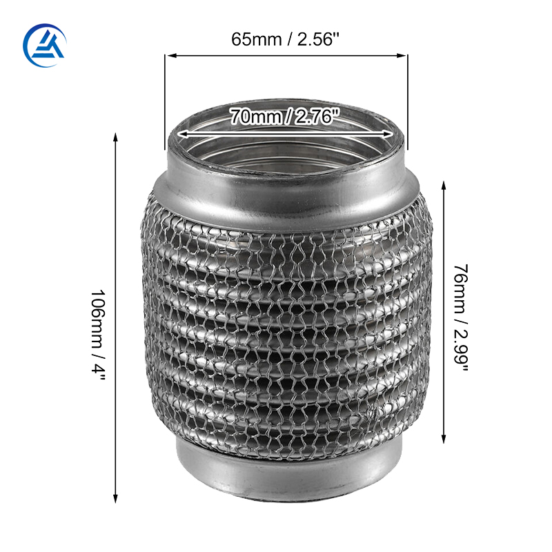
How a Car Exhaust Flex Joint Absorbs Multi-Directional Stress
Automotive engineers design flexible couplings to manage highly dynamic forces. A car exhaust flex joint operates as a sophisticated mechanical buffer. It actively resolves three distinct types of kinetic stress simultaneously.
Axial Movement: Exhaust pipes push and pull linearly. The entire pipe lengthens during intense heating cycles. It subsequently contracts during cooling cycles. The corrugated outer bellows compress and extend safely. This motion absorbs the linear dimensional change without binding.
Lateral and Angular Deflection: Engines do not sit perfectly still. They roll aggressively during heavy acceleration and sudden deceleration. Engineers call this torque deflection. The flexible joint bends laterally to compensate for this severe engine movement. It prevents torque forces from snapping rigid pipe sections or tearing chassis hangers.
Vibration Isolation: Engine blocks generate constant harmonic vibrations. Static chassis mounts cannot dampen these specific acoustic frequencies effectively. The flex joint decouples this harsh kinetic energy. It stops engine vibrations from transmitting directly into the passenger cabin. This dramatically reduces NVH (Noise, Vibration, and Harshness). It also prevents long-term structural fatigue along the metal chassis.
What to watch out for: A flex joint cannot fix broken engine mounts. If your engine moves excessively due to torn mounts, the flex joint will overextend and tear. Always inspect engine mounts when replacing a failed flexible pipe.
Evaluating Stainless Exhaust Flex Materials and Construction
Material choices directly dictate component longevity. You must evaluate the heat and corrosion matrix carefully before sourcing parts. Cheap alternatives fail quickly under extreme operating parameters.
Alloy Grading (The Heat & Corrosion Matrix)
Many aftermarket manufacturers use aluminized steel to cut costs. Aluminized steel fails rapidly under high-heat thermal cycling. The thin aluminum coating literally burns off at high temperatures. The exposed mild steel underneath then rusts and cracks within months. You must specify a stainless exhaust flex for true durability.
Different stainless steel grades offer vastly different performance ceilings. You must match the alloy to your specific application.
Table 1: Stainless Steel Alloy Grades and Thermal Thresholds
| Alloy Grade | Primary Characteristics | Operating Temperature Limit | Best Application Use Case |
| 304 Stainless | Good corrosion resistance, prone to carbide precipitation. | Up to 800°C (1,470°F) | Standard naturally aspirated passenger vehicles. |
| 316 Stainless | Added molybdenum for superior road salt corrosion resistance. | Up to 850°C (1,560°F) | Coastal environments or regions heavily salting winter roads. |
| 321 Stainless | Titanium stabilized. Prevents intergranular corrosion entirely. | Up to 900°C+ (1,650°F+) | Turbocharged engines, commercial fleets, extreme motorsport. |
We highly recommend 321 stainless for turbocharged applications. The titanium addition makes it vastly superior for extreme heat environments.
Internal Liner Architecture
The internal construction dictates exhaust flow efficiency. It also determines how well the unit resists high-velocity gas degradation.
No Liner: Bare corrugated bellows create massive turbulence. High-velocity gas hits the ridges. This creates a high risk of bellows whistling. The turbulent gas also causes premature wear on the thin corrugations.
Inner Braid: Manufacturers weave stainless steel wires inside the bellows. This design remains cost-effective. It works well for standard naturally aspirated engines. However, high backpressure easily frays the braided wire. Frayed wires then block exhaust flow.
Interlock Liner (Spiral Wound): This represents the gold standard for durability. Machines wind solid stainless steel strips into a flexible interlocking hose. It allows incredibly smooth gas flow. It protects the fragile outer bellows completely. It withstands extremely high exhaust velocities without degrading or fraying.
Chart 1: Internal Liner Architecture Comparison Chart
| Liner Type | Flow Efficiency | Durability Rating | Primary Risk Factor |
| No Liner | Poor (High Turbulence) | Low | Acoustic whistling and rapid ridge fatigue. |
| Inner Braid | Moderate | Medium | Wire fraying under extreme backpressure or heat. |
| Interlock Liner | Excellent (Smooth Flow) | High | Higher initial procurement price. |
Implementation Risks: Sizing, Placement, and Installation
Even the best components fail upon improper installation. You must navigate specific integration challenges carefully.
Proximity to the Heat Source
Placement geometry matters immensely. You must position the flex pipe close enough to the engine to absorb immediate torque. Placing it too far downstream renders it useless against engine roll. However, you must factor in material heat limits. Placing it directly adjacent to a catalytic converter risks disaster. Converters generate massive radiant heat. This proximity can easily exceed the thermal threshold of the flexible bellows.
Sizing Inaccuracies
Selecting the wrong size introduces severe mechanical risks. Sizing the internal diameter too small creates an immediate bottleneck. This restricts exhaust flow entirely. Restricted flow spikes engine temperatures and kills horsepower. Conversely, sizing the flexible section too long removes vital structural support. A disproportionately long flex joint allows the heavy exhaust line to sag. Sagging places unbearable strain on downstream rubber hangers.
Welding and Joining Realities
Installation requires precise fabrication techniques. You must use purge welding when joining stainless steel components. Purge welding involves flooding the inside of the pipe with inert argon gas during the weld. This critical step prevents internal oxidation. Without purge gas, oxygen reacts with the molten stainless steel. This creates porous, brittle slag inside the pipe (often called "sugaring"). Sugaring restricts flow and creates weak joints. Proper purge welding ensures a strong, hermetic seal.
Common Mistakes: Mechanics often use standard MIG wire on stainless steel. You must use the correct stainless filler rod (like ER308 or ER347). Incorrect filler metal causes the weld seam to rust and crack rapidly.
Shortlisting Criteria for Procurement and Upgrades
Sourcing reliable components requires a systematic approach. You must evaluate vendors critically to avoid substandard parts.
Quality Assurance Checkpoints
You can spot sub-par units through careful visual inspection. Examine the outer bellows material first. Cheap units use dangerously thin metal that dents easily under thumb pressure. Next, inspect the spot-welding on the end collars. Manufacturers must weld the inner liner, outer bellows, and braided covers to the end caps securely. Poor, misaligned spot-welds break loose under heavy vibration. The joint will unravel internally if these welds fail.
Compliance and Certification
Commercial fleet operators and performance builders must demand strict certifications. Ensure the manufacturer meets ISO 9001 quality management standards. High-end applications often require OEM equivalent specifications (like TS 16949 compliance). Certified manufacturing guarantees predictable material grades. It also ensures consistent safety margins across bulk orders.
Next Steps
Use this practical checklist before ordering your replacements:
Measure the exact outer diameter (O.D.) of your existing rigid pipe. Your new component must match this exactly for a flush weld.
Calculate the required flex length carefully. Measure from straight-pipe to straight-pipe, avoiding curved sections.
Determine peak exhaust gas temperatures (EGT) for your specific engine platform.
Select the correct alloy grade (304, 316, or 321) based directly on your EGT data.
Verify the internal construction. Specify an interlock liner for any turbocharged or heavy-duty application.
Conclusion
An exhaust flex pipe operates as far more than a simple connector. It serves as a critical mechanical safeguard against extreme thermal expansion and violent vibration. Rigid exhaust systems inevitably fracture under the immense strain of constant thermal cycling. Prioritizing robust interlock construction yields superior gas flow and unmatched durability. Selecting appropriate stainless steel grades protects your entire system from premature heat degradation. When you source and install these components correctly, you gain the best possible return on your investment. A high-quality flexible joint effectively protects your expensive downstream components from catastrophic structural failure.
FAQ
Q: Can I use a solid pipe instead of an exhaust flex pipe?
A: No. A solid pipe cannot absorb engine torque or thermal expansion. The trapped kinetic energy will transfer directly to the weakest structural points. This leads to inevitable, severe stress fractures at the exhaust manifold, turbocharger housing, or chassis hangers.
Q: What is the lifespan of a high-quality stainless exhaust flex pipe?
A: The lifespan depends entirely on operating conditions and material selection. They typically last between 50,000 and 100,000 miles. Premium 321 stainless steel units featuring an interlocking liner significantly outlast standard 304 braided variants under harsh conditions.
Q: How do I know if my car exhaust flex joint is failing?
A: You should look for visible black soot or carbon buildup around the braided wire mesh. You will likely hear a noticeable increase in engine noise, such as loud hissing or metallic rattling. You may also smell dangerous exhaust fumes inside the passenger cabin.
Q: Does the inner liner type affect exhaust gas velocity?
A: Yes. An interlock liner maintains a smooth, consistent internal diameter. This specialized construction dramatically reduces gas turbulence and internal backpressure. It performs vastly better compared to an exposed corrugated bellow or a frayed inner braided wire.


